Features
Architectural design
Contracting
No worries window wall – tips and tricks to make window wall work well
Some approaches to overcoming performance challenges in window wall
October 10, 2017 By George Torok and Yvon Chiasson Morrison Hershfield.
 Window wall has surged in popularity with designers because of its ability to deliver wide-open vistas and indoor/outdoor living spaces. But integrating it into typical building envelope designs has been a learning process for many contractors. As the industry’s experience with these products increases, new ideas are emerging for how to make window wall better. Photo: Getty Images
In August Glass Canada, we discussed the development of window wall systems and the relevant past and current building codes and standards.
This month, we look at examples of installation detail, showing examples of past practice and current good practice, highlighting state-of-the-art techniques that leaders in the window wall industry are using to take performance to a higher level.
Structure and anchorage
Attachment methods for Canadian window wall systems evolved from methods originally used for punched windows set into two-wythe face brick on concrete block mass walls. Strap anchors are still favoured by many Canadian window wall manufacturers because of their flexibility, allowing installers to adjust variations in the frame to structure gaps by bending or repositioning the strap (when it isn’t fixed in place) if the fastener installation is frustrated by hard aggregate or embedded reinforcing steel. The length of the strap anchors is usually short to minimize interference with the interior finishes. These benefits can also be a liability if the strap is too short to bridge the frame over the structure gap. Another danger is that repositioning straps may compromise their structural performance.
Strap anchors at the head have flexibility for vertical movement but little for lateral movement, such as might be caused by seismic activity. In seismically active regions, some manufacturers have adopted head receivers (and in some cases, jamb receivers) such as may be found in American-style window walls. Receivers may also have benefits because they allow easier relocation of the fasteners away from the design locations to avoid hard aggregate, embedded reinforcing steel, damaged concrete and similar obstacles. To accommodate variations in floor-to-floor height, head receivers can be shimmed down from the slab soffit to provide the required overlap to the head rail.
At the floor slab, it is common to secure window wall systems with a continuous, extruded aluminum back angle, fastened to the sill rails and the bottoms of mullions with self-drilling, self-tapping screws, and to the floor slab with concrete screws. Since these connections are rigid, allowance for building frame shrinkage and creep, thermal movement, inter-storey drift and seismic movement can occur only at the head and jambs. Variations in floor-to-floor height may lead to the problems with the strap anchors being too short to overlap the sill rail for installation of the anchors, requiring an on-site adjustment.
Window wall panels are often manufactured in widths similar to unitized curtain wall panels: 48 to 60 inches wide, or the typical width of one fixed-glazed insulating glass unit or operable window. The panel width is limited by the rail’s capacity to support the dead load of the insulating glass units to within allowable deflection amounts; by the overall panel weight that can moved manually and by hoist; and by the overall panel size that can be accommodated by shipping services, along with other factors. Adjacent panels are joined together by some form of mechanical interlock between the jamb mullions. These methods vary by manufacturer. One common approach is to nest the open-back mullions with one mullion being slightly deeper than the mating mullion on the adjacent panel. Another is to use connector plates that are H-shaped in cross-section (called H-bar connectors) that slip over the exterior and interior faces of the open back mullions, tongue-and-groove style. These joining methods typically increase the depth of the mullions beyond the exterior and interior faces of the rails, which can cause some difficulties when installing air and water seals and heads and sills, as will be described later.
Where window walls pass in front of columns and shear walls there may be conflicts with the installation of the strap anchors, head receivers and back angles. It may be possible to offset the strap anchors laterally, but the head receivers and back angles must be continuous not only for structural anchorage but also to maintain the air- and water-tightness of the wall/window interface. Columns and shear walls should be recessed behind the slab edge sufficiently for the anticipated width of the anchor system plus working room to install fasteners and also for the air- and water-leakage control membranes, sealants and other materials. This requires careful forethought during architectural and structural design. Unfortunately, the window wall manufacturer may not be selected early enough in the construction process to provide the necessary design input, so modifications may need to be made on site. Any modifications affecting the structure of the wall panels should be reviewed and approved by a licensed design professional.
A defining feature of Canadian window wall is the slab bypass. Typically, the sill extrusion inboard of the thermal break is anchored to the upper surface of the slab with a continuous back angle and mullion extrusions. The sill extrusion outboard of the thermal break is extended down to the head rail of the window panel below, concealing the slab edge. In early window wall systems, the bypass was face-sealed with composite panels consisting of metal skins sandwiching a rigid core (either extruded or expanded polystyrene) glazed into the frame from the exterior. Such systems often had poor water-leakage resistance. Today, most Canadian window wall systems employ rainscreen design principles, including at the bypass. The spandrel infill is a cladding that needs to resist gust wind loads. Air leakage and water penetration control are provided by waterproofing membranes and sealants behind. These functions will be discussed in more detail later.
Controlling air and water
As surrounding wall systems have changed from mass masonry construction to rain screen systems, window design and assembly and installation detailing has also changed. Today, most Canadian window wall systems are designed and installed according to the rainscreen principle. This consists of designing the systems so that exterior surfaces and sealants present a deterrent to precipitation ingress with the barrier air and water seals located inboard. This protects the barriers from direct wetting, gust wind pressure, solar radiation and other damaging factors, which promotes long service life. The interstitial space between the exterior surfaces/sealants and the internal seals is typically vented to moderate wind pressures and drained to remove moisture that may penetrate behind the exterior.
Generally, window wall panels are factory prefabricated with the infill glazing, vents and spandrel panels. On-site fabrication is limited to connection details such as the inside and outside corners and the junctions to adjacent enclosure systems. Frame openings are individually sealed, drained and vented to the exterior. Cascading, internal drainage to a sub-frame or sill pan that is wept to the exterior is common in the U.S., but unusual in Canadian window wall systems. However, allowance for leakage through the frame joinery and through the interface joints between the window wall system and the adjacent wall systems is provided at the sill. The interface joints are typically waterproofed with gunned, liquid-applied sealants (caulking, bead-applied polyurethane foam) and membranes (self-adhesive, field-applied adhesive and/or thermofusible). Window wall systems used on the Canadian west coast and bound for the U.S. are likely to incorporate head receivers and sometimes jamb receivers instead of gunned sealants and membranes.
The insulating glass units are typically laid-in glazed from the building interior side of the frame. The rainscreen design at the perimeter of the insulating glass units is accomplished with gunned, liquid-applied sealants and/or preformed elastomeric rubber gaskets around the full perimeter of each unit to the surrounding frame mullions and rails. Each frame opening in a window wall assembly (both in the vision and opaque areas) is usually wept directly to the outside through openings in the horizontal rails below, similar to a rainscreen-designed curtain wall. Opaque areas (spandrel panels) are constructed similar to Canadian-style rainscreen curtain walls with a sheet metal backpan sealed to the surrounding mullions and rails, with the insulation mechanically secured to the outside face of the backpan and with a cladding at the exterior glazed into the surrounding frame. The interstitial space is drained and vented to the exterior.
When the strap anchors project beyond the interior of the building interior face of the window wall system they breach the interior seal at the head and often at jambs, also. To maintain air leakage and water penetration control, each strap must be carefully encapsulated, which is tedious, time consuming and expensive work. It is difficult to apply sealants to the edge of open back frames because the frame edge is narrow and provides little bond area for the sealant to the frame. A more robust fillet bead application to the room-side face of the frame provides more certainty of adhesion and long-term performance. However, such sealant application may interfere with interior finishes. An alternative is to use a head receiver with preformed elastomeric rubber seals to the frame head to permit inter-storey drift and seismic movements and gunned, liquid-applied sealants for the static connection between the head receiver and the structure. Head receivers are available from most manufacturers serving the Canadian west coast markets. Some manufacturers can also supply jamb receivers.
At the sill, air- and water-leakage control is typically provided by application of a membrane over the edge of the floor slab behind the slab bypass, extending from a head flashing or head receiver above the panel on the floor below to the vertical upturn leg of the continuous back angle used to anchor the sill. The membrane upturn is sealed to the window wall sill rail with gunned, liquid-applied sealant. The quality of the back angle membrane or window wall sill rail seal can be affected by the joining method between adjacent window wall panels. As described previously, nested mullions or H-bar-connected mullions are deeper than the rails. When the mullions are set against the back angle, gaps are created between the upturned membrane on the back angle and the rails. The gaps must be filled with sealant. A common installation technique is to apply sealant to the membrane upturn prior to moving the panels into place, relying on squeezing of the sealant to fill the joint. This “smash glazing” approach may not completely fill the gaps. A similar problem occurs at the head when head receivers are used. Preformed elastomeric rubber gaskets typically provided between the receiver and the window wall panels must be sufficiently flexibile to seal the narrow gaps at the mullions and the wider gaps at the rails. These installation techniques should be reviewed carefully during construction and the method adjusted if inadequate sealing is detected.
A weakness of using different methods to seal the interface joints between the window wall perimeter and adjacent wall systems at sill, jamb and head is ensuring continuity at the junctions. Architectural and window wall manufacturer shop drawing details are almost exclusively two-dimensional, so junctions between different sealant systems must be discerned through careful study. If not addressed in the drawing review stage, the installer is left to figure out a solution on site. The knowledge, experience and skill of the installer greatly affects the quality of the solution, which can range from simply applying more gunned sealant to bridge or fill gaps to well-thought-out and installed flexible membranes or brake-shaped aluminum closures. In this regard, the common approach in the U.S. of using head and jamb receivers and a sub-frame or sill pan at the sill, designed as a system with similar components, is superior to the Canadian approach.
To be fair, it should be noted that the success of window wall systems in the U.S. also relies to a great extent on gunned, liquid-applied sealants to prevent air and water leakage. Both families of window wall systems need good design and diligent shop and site personnel to correctly assemble and install the frames and infill. A good quality assurance program should identify issues of concern in the shop and on site to ensure successful performance of the window wall and the building envelope as a whole.
-

- Window wall has surged in popularity with designers because of its ability to deliver wide-open vistas and indoor/outdoor living spaces. But integrating it into typical building envelope designs has been a learning process for many contractors. As the industry’s experience with these products increases, new ideas are emerging for how to make window wall better.

Installation dos and don’ts
Closing the gap
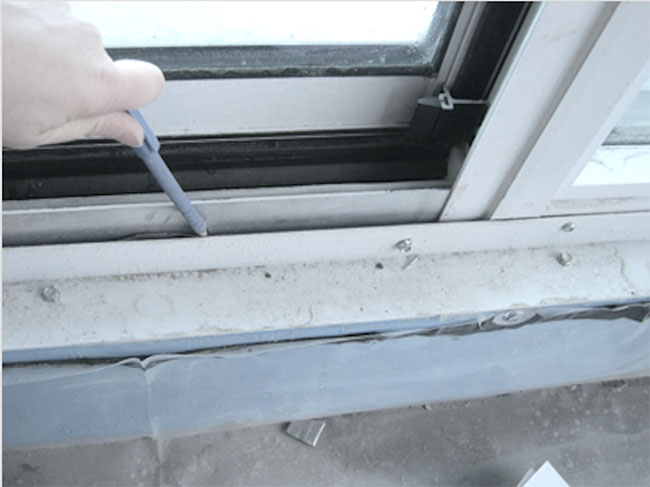
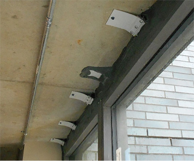
Examples of strap anchors at the head rail of a window wall. On the top, the straps are secured with concrete screws to the underside of the floor slab with one-component polyurethane foam air sealant foam in the rough opening gap as an air seal. On the bottom, the rough opening gap exceeds the length of the strap so the straps are extended by stitching them end-to-end. A gunned sealant was applied over the foam to ensure the continuity of the air barrier. Encapsulating the perimeter of the straps might be needed if it is hard to get behind the strap to apply sealant.
PLAN AHEAD
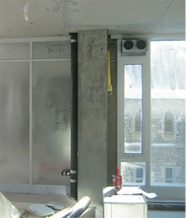
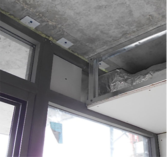
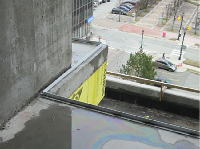
Examples of interference/lack of coordination between the structure, mechanical services and window wall systems. On the left, the column was not recessed to allow the window wall frame to pass in front. The installer’s solution was to cut away horizontal components including the rails and head receiver. On the right, the kitchen and bathroom exhaust duct bulkhead was installed before the head rail and the underside of the floor slab joint air seal was complete.
KEEP IT DRY
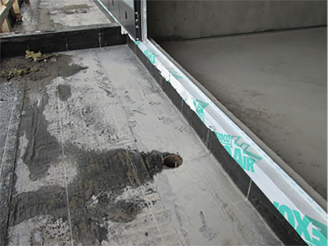
Examples of a continuous sill angle with self-adhesive membrane waterproofing on the exterior.
On the top, a continuous angle is installed at the edge of the floor slab. On the bottom, a membrane was installed at the curb on a balcony with the self-adhesive membrane overlapping the thermofusible waterproofing membrane for the balcony.
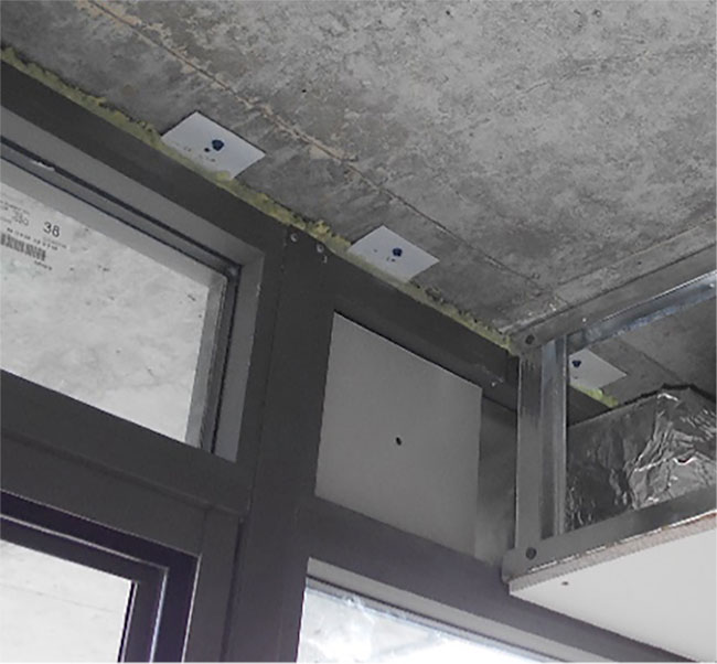
Think in three dimensions
Careful thought in 3D is required to ensure continuing of air- and water-leakage control. On the left, a head receiver butts against a self-adhesive air barrier and WRB returned into the rough opening from an adjacent envelope enclosure system. A gunned sealant was applied to ensure continuity. On the right, at another junction condition, the continuous sill angle and self-adhesive waterproofing membrane are extended past the jamb mullion into the adjacent wall assembly. Continuity between envelope systems was not adequately considered during design and construction.
Print this page